Understanding Analog Ammeters: A Comprehensive Explanation
Analog ammeters are among the oldest types of instruments used to measure electrical current, and their workplace can still be found in various settings today. While digital multimeters have gained significant popularity, understanding how analog ammeters work provides a solid foundation in the principles of electrical engineering.
These devices play a crucial role in quickly assessing electrical circuit safety and ensuring the equipment operates within its specified range. So, let's explore the fundamental mechanics behind these meters and how they help us monitor electrical currents effectively.
Fundamental Components of an Analog Ammeter
At its core, an analog ammeter comprises three primary components: a moving coil, a permanent magnet, and a pointer. These elements collaborate to indicate the magnitude of the current flow through the meter.


Moreover, analog ammeters are typically calibrated in Amperes (A), the Standard International (SI) unit for electrical current. The scale on the dial usually spans from 0 to a maximum value, depending on the meter's rating.
Moving Coil and Permanent Magnet
The moving coil, enjoying its perch at the heart of the ammeter, is formed by winding an insulated wire around a soft iron core. This coil is arranged such that when a current flows through it, the resulting magnetic field interacts with the flux of the permanent magnet positioned alongside it.

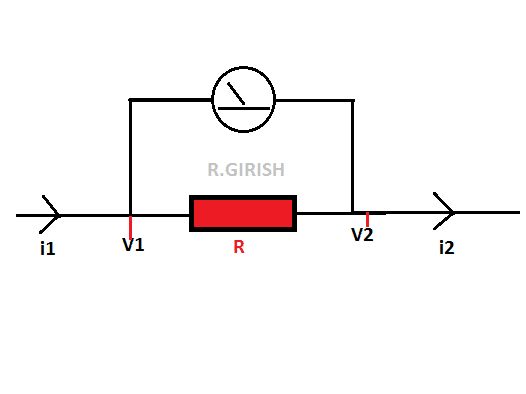

The direction and magnitude of the current affect the moving coil's torque. This relationship is defined by Ampere's law, which states that the magnetic moment (or torque) of a current-carrying coil in a magnetic field is directly proportional to the current's strength. This principle forms the basis of an analog ammeter's operation.
Pointer and Scale
The moving coil is affixed to a pivot, allowing it to rotate freely. Connected to this coil is a pointer or needle, which moves across a calibrated scale as the coil rotates. The scale is mounted in such a way that when the coil does not carry any current, the pointer points to the '0' mark, signifying no current flow through the meter.
As the current magnitude changes, the torque on the coil also varies, causing the pointer to move along the scale. The deflection of the pointer is directly proportional to the current, thus allowing us to measure and interpret the electrical current's magnitude using an analog ammeter.


Integrating an Analog Ammeter into an Electrical Circuit
Analog ammeters are always connected in series within an electrical circuit, which allows the test current to flow through the meter directly. Since they measure in terms of amperes, they do not require any voltage reference for calibration purposes.
However, these devices are typically sized based on the current range they are designed to measure. In other words, selecting the appropriate ammeter for a given circuit is crucial to avoid overloading the meter or underutilizing its capabilities.
Loading Effects: Picking the Right Ammeter
Connecting an ammeter to a circuit may impose loading effects, where the meter's presence slightly alters the circuit's current or voltage. A higher-impedance ammeter will introduce less disturbance to the circuit, thus retaining its integrity better. Low-impedance meters, on the other hand, may cause more significant fluctuations in the voltage level.


Therefore, when choosing an analog ammeter, it's essential to pick one with the correct full-scale value (e.g., 5A, 10A, 20A) for the likely current range, and select an adequately high-impedance one to minimize loading effects on the circuit.
In conclusion, analog ammeters play an essential role in assessing electrical currents in many settings. While they might be less common today with the advent of digital multimeters, understanding the principles behind their operation remains critical. As we continue to harness and manage electrical currents more efficiently, these meters' functionalities remain integral to our technological advancements.


