Sizing Transformers: A Step-by-Step Guide to Calculate Wire Size
Determining the appropriate wire size for a transformer is a critical step in ensuring optimal performance, system reliability, and safety. The wire size influences the system's capacity to handle current and voltage drops, making it essential to select the right size for your transformer. This guide will walk you through the process of calculating wire size for transformers, step by step.
Before we dive into the calculations, let's ensure you understand some key terms. The wire's cross-sectional area is the crucial factor determining its current-carrying capacity. This area, often denoted as A, is measured in square millimeters (mm²). Another vital parameter is the wire's length, L, which is typically given in meters. Additionally, we'll need to know the current, I, that the wire will carry and the allowed voltage drop, VDrop, across the wire.
Understanding Wire Gauge and Current-Carrying Capacity
The wire gauge, typically denoted as SWG (Standard Wire Gauge), is a measure of the wire's diameter, and thus its cross-sectional area. To work with these values, it's essential to know the relationship between SWG and the cross-sectional area in mm². For example, a 16 SWG wire has a cross-sectional area of approximately 1.3 mm², while a 7 SWG wire has around 16 mm².

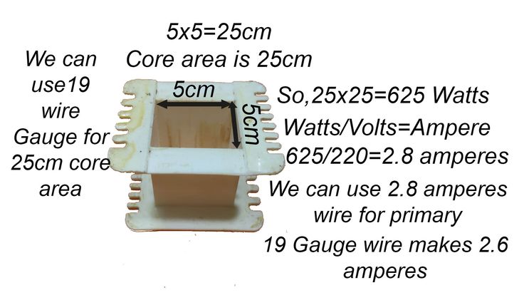

Wires have a maximum current-carrying capacity (also known as allowable current) at varying temperatures. This value is determined by most countries' regulations and is often listed in tables or charts. Ensure you use the correct value for your region and application. For our calculations, we'll assume a 70°C temperature rise for cupro-nickel and aluminum wires and a 60°C rise for copper wires.
Calculating the Wire Size: Method 1 - Voltage Drop Method
The voltage drop method calculates the wire size based on the maximum allowed voltage drop across the wire. This method is suitable when you know the allowed voltage drop. To begin, you'll need to calculate the resistance of the wire. The formula for resistance, R, is:


R = ( ρ * L ) / A
Where ρ is the material's resistivity ( measured in ohm-meters), L is the wire length, and A is the cross-sectional area. The resistivity values for common wire materials are: 2.83 × 10^-8 ohm-meters for copper, 2.9 × 10^-8 ohm-meters for aluminum, and 1.56 × 10^-7 ohm-meters for cupro-nickel.
Next, rearrange the voltage drop formula ( VDrop = R * I ) to solve for the cross-sectional area:


A = ( ρ * L * I ) / VDrop
Lastly, round up the cross-sectional area to the nearest standard value (determine the SWG).
Calculating the Wire Size: Method 2 - Current Method
In this method, you calculate the wire size based on the current-carrying capacity required. First, determine the required current-carrying capacity (I) based on your system's and application's needs. Then, use the following formula to find the cross-sectional area:


A = ( I * ρ * L ) / ( k * ( TD - TA ) )
Where k is a constant depending on the wire's thermal conductivity (0.13 for copper, 0.105 for aluminum, and 0.07 for cupro-nickel), TD is the maximum allowable temperature (70°C or 60°C), and TA is the ambient temperature.
Round up the cross-sectional area to the nearest standard value (determine the SWG).
The Importance of Safety Factors and Tolerances
When selecting a wire size, it's crucial to consider safety factors and tolerances. These account for variations in material properties, installation lengths, and unforeseen system demands. Always select a wire with a cross-sectional area larger than your calculated value by a certain factor. Common safety factors are 1.25 and 1.5, but they may vary depending on your country's regulations or application-specific guidelines.
Additionally, ensure that the wire cross-sectional area meets or exceeds any minimum size requirements set by your country's electrical codes or local regulations. For example, many codes require a minimum wire size for certain circuit types or loads.
Finally, always check the wire's data sheet or the manufacturer's guidelines to ensure that your selected wire can withstand the application's voltage and current requirements within its specified temperature range.
Selecting the correct wire size for your transformer is an essential step in ensuring the longevity, performance, and safety of your electrical system. By following these guidelines and performing the necessary calculations, you'll make an informed decision that meets your system's needs and complies with relevant regulations.


