Auto Cut-Off Battery Charger Circuit: Safe and Efficient
Isn't it frustrating when you leave your battery charger plugged in after your device is fully charged? Not only does it cost you extra in electricity bills, but it also reduces the lifespan of your battery. This is where a battery charger auto cut-off circuit comes into play. This ingenious circuit automatically stops charging your device once it's full, saving you money and preserving your battery's health.
In today's world, where sustainable living and conscious energy usage are vital, every bit of efficiency makes a difference. Let's dive into the world of battery charger auto cut-off circuits, understanding their functionality, components, and how to create one for your own devices.
The Need for Battery Charger Auto Cut Off Circuits
Batteries have a finite capacity to store energy. Once they're full, any excess charge does more harm than good. Charging beyond this point generates excess heat, which can degrade your battery over time. A battery charger auto cut-off circuit solves this issue by monitoring the charging process and stopping it once the battery is full.


These circuits not only extend the life of your batteries but also enhance the safety of your devices by preventing overcharging-related accidents. They are increasingly becoming an integral part of modern battery chargers, from portable devices like smartphones and laptops to electric vehicles and energy storage systems.
How Do Battery Charger Auto Cut Off Circuits Work?
At its core, a battery charger auto cut-off circuit constantly monitors the battery's voltage. It includes a comparator IC that compares the battery's voltage with a predefined threshold, typically around 4.2V for lithium-ion batteries. When the battery voltage reaches this threshold, the circuit opens a switch (usually a MOSFET) in the charging path, disconnecting the charger from the battery.
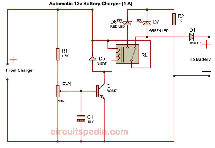


Some advanced circuits also include features like overcurrent protection, which stops the charging process if the current exceeds a safe limit. Others offer thermal protection, halting the charging process if the battery or charger overheats. These additional features provide an extra level of safety and longevity for your batteries.
Components Needed to Build a Battery Charger Auto Cut Off Circuit
To build a simple battery charger auto cut-off circuit, you'll need a few basic components. These include a comparator IC, resistors, a diode, and a MOSFET. Discrete components are used for simplicity, but integrated solutions, such as the MCP1640 from Microchip, are also available, reducing the bill of materials and design complexity.
Here's a simple bill of materials for a basic battery charger auto cut-off circuit: -Comparator IC (e.g., LM393) -A N-channel MOSFET (e.g., IRF840) -Resistors (10kΩ, 4.7kΩ, 1kΩ, and 100Ω) -A diode (e.g., 1N4007) -A 10μF capacitor


Types of Battery Charger Auto Cut Off Circuits
Depending on the battery type and charger complexity, different auto cut-off circuits can be used. Let's explore a few common types:
Voltage-Based Auto Cut-Off Circuits
The most common, and simplest, type of battery charger auto cut-off circuit uses a comparator to monitor the battery's voltage. Once the battery voltage reaches a certain threshold, the comparator triggers the MOSFET to cut off the charging supply. This type of circuit is easy to build and suitable for most low-voltage battery applications.
However, it's essential to consider the charger's efficiency and stability. If the charger supplies a far higher voltage than the battery's nominal voltage, the comparator could false-trigger, leading to undercharging. Balancing efficiency and stability is crucial when designing voltage-based auto cut-off circuits.


Mixed Mode Auto Cut-Off Circuits
As battery technology advances, so do the charging methods. Modern batteries like Lithium-Ion and Lithium-Polymer (LiPo) require more complex charging protocols. Mixed-mode auto cut-off circuits address this by using a mix of voltage and current sensing.
In these circuits, a microcontroller monitors the battery's voltage and current, implementing the charging profile according to the battery's type. Once the battery reaches its full capacity, the microcontroller sends a signal to the MOSFET, stopping the charging process. This approach improves charging efficiency and prolongs battery life.
Mixed-mode auto cut-off circuits are more complex and expensive than voltage-based ones, but they offer superior performance and are well-suited for high-end applications like electric vehicles and energy storage systems.
The Role of Auto Cut-Off Circuits in Modern Battery Charging Systems
As battery technology evolves, so do the charging systems that support it. Modern battery chargers incorporate various features, including temperature compensation, faster charging, and better safety protection. Auto cut-off circuits play an integral role in these advanced systems.
For instance, in a constant current-constant voltage (CC-CV) charging system, the auto cut-off circuit works in tandem with the CC and CV stages. The CC stage provides a constant current until the battery's voltage reaches a predefined threshold. At this point, the CV stage takes over, maintaining a constant voltage until the current drops to a safe level. The auto cut-off circuit then stops the charging process, preventing overcharging.
Therefore, while the primary function of an auto cut-off circuit is to prevent overcharging, its role extends to supporting the overall charging process and ensuring safe, efficient, and long-lasting battery operation.
In the vast landscape of battery charging systems, auto cut-off circuits stand as unsung heroes, silently safeguarding your batteries and contributing to a robust, efficient, and sustainable future. As we continue to innovate and push the boundaries of battery technology, these circuits will remain a cornerstone of any reliable and safe charging system.


